Category Archives: DIY Tractor

KA metamorphoses to DT. Longer explanation is that I decided to convert one front crashed Ford KA to Do It Yourself Tractor.

Preparing the diff welding

Yesterday I was investigating my Sierra’s steering since it has started to keep annoying noise sometimes when turning the wheel and seems that there are something wrong with the tie rod… So I prepared a spare tie rod from my parts stock pile ready which I will remove&replace next Monday.

Today I built a fork that I will use to press diff bearing out from the speedo gear side:

20140805_194157My plan is to first weld the diff gears very lightly together with the drive shafts in to get the gear positions correctly. Then I will remove the driveshafts, speedo gear and bearing from speedo gear side. The big gear and bearing behind it I will leave in place. I will try to limit the amount of heat somehow, probably I need to weld at small parts and wait for cooling.


Opening Ford IB5 Gearbox

Since the driveshaft outputs from the gearbox will be working as cardan axles instead of being driveshafts I decided that I need to do something to the diff inside IB5 gearbox.  Without doing anything to the diff the 4×4 drive system would be flawed since only the wheel that is rotating most easiest (the wheel on air usually) would get all the power.

So basically without any locks at diffs only one wheel of four would get the power and the tractor would be rather crippled. Now when I weld this “center diff” there will always be two wheels getting the power. One at front and one at rear. So this will be continuous 50% / 50%  4×4 vehicle (front/rear).

And at rear I do have viscous lock inside the diff so basically there will always be 3 wheels getting the power, two at rear and one at front. Only slight issue is that the rear viscous lock is broken since the seal has leaked and the silicone oils and diff oils have mixed. But that I will fix some day later…

But now back to the topic and opening the IB5 gearbox. I found this nice instruction after some Googling:

http://www.quantums.info/gearbox.htm

And I started to follow it and opened the rear section (5th gear housing):

20140803_111008

To get that left gear out I needed to build a special puller tool since I did not had one for this purpose. 20140803_111021After I removed the 5th gear gears, selector and the housing it looked like this:

20140803_165419The next task was to remove the actual gearbox casing:

20140803_170727And after I removed input & output shafts, 1-4 gear selector and the diff it looked like this:

20140803_172508Next task is to weld the diff:

20140803_172520But unfortunately I did not had anymore time to continue work today so this will continue later…


Ford IB5 gearbox 5th gear DIY puller

I needed to open IB5 gearbox taken out from Ford Ka. After opening the rear section and removing a couple of parts I noticed that I cannot go any further without a proper puller tool. Unfortunately I did not had one for this need, but fortunately this wasn’t the first time such issue occurs. 😉

So I started to create a puller tool for the fifth gear:

20140803_125511I started with cutting a fork from  stainless steel since it is a little bit stiffer than regular steel. Regular steel would probably have worked as well, so it was a bit overkill to use stainless steel I believe.

Here is a photo of ready product:

20140803_144331Not that pretty since I did not grind any corners or did any finishing to it. Maybe someday later….

But it worked as expected and now I have IB5 fifth gear puller:

20140803_164056If somebody is creating something similar I recommend using M16x1  thread instead of standard M16x2. I would used that, but I don’t have tooling to create such threw. But even with this coarse threw the tool was able to do its job very nicely.

And just in case you wonder about the standard M threads, here is a rather nice table about those:

http://www.shender4.com/metric_thread_chart.htm


Planning the tractor powertrain

I have spend some good time to fiddle with the parts I have in my garage and decided that I will use 4×4 Sierra front wheel mounts and CV joints even my original plan was to use Ka’s parts for those.

It turns out that 4×4 Sierra front outer CV joint is almost perfect fit to Sierra’s small plug-able rear drive shaft:

20140731_154852

20140731_154904

This is very good news since now I don’t need to cut Ka drive shafts and weld it to those Sierra’s drive shafts to be ably to use Sierra’s diffs. Instead I can use standard parts already available, only a slight reconfiguration is needed.

My intention was to avoid using 4×4 Sierra front parts since they are becoming rare and replacing them may not be so easy at future. But since this is so nice fit and I have the parts I will use those. This means Sierra’s 240mm brake discs + calibers and all the wheel mount parts except the suspension parts. Those discs are the same size as Ka’s, but with that difference that they have some additional cooling (which is totally unnecessary for this project).

Now since I will have complete Ka drive shafts I stated to think that maybe I can minimize the need for custom parts with those… And then I figured out that I will only need two flanges that need to be lathed. This is the plan for front diff:

20140731_201808 20140731_201821

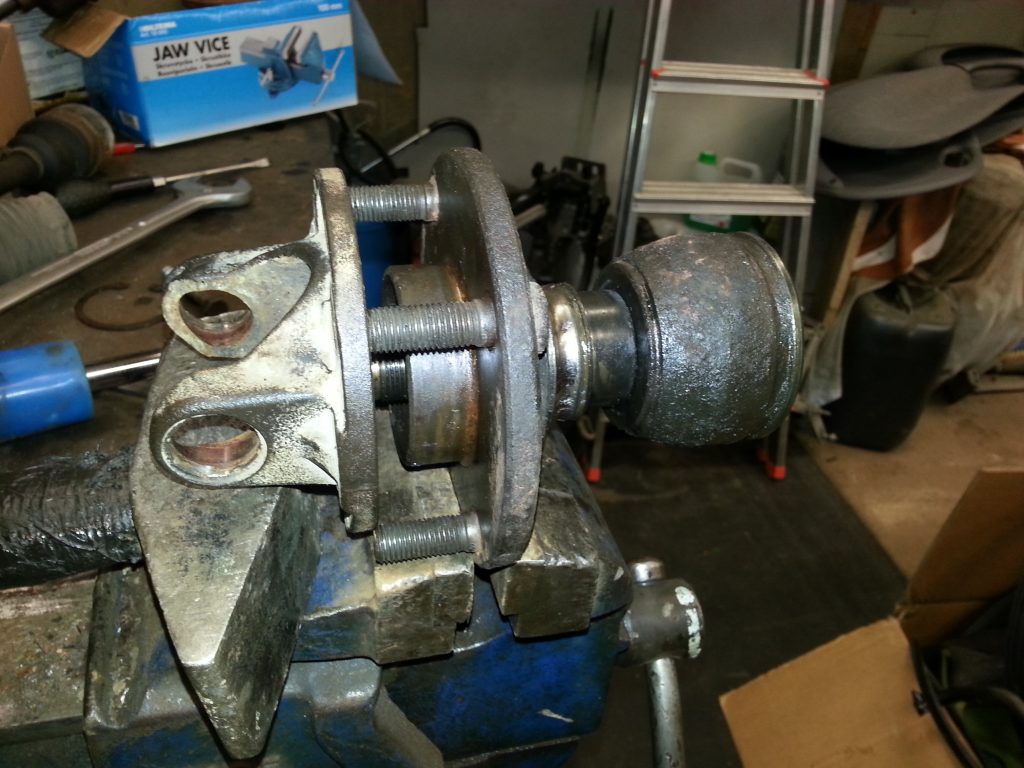
That cardan shaft flange represents the mount at diff itself at these pictures. It means that with this CV joint + wheel hub I only need one flange to be machined to be able to bolt it to the front diff.

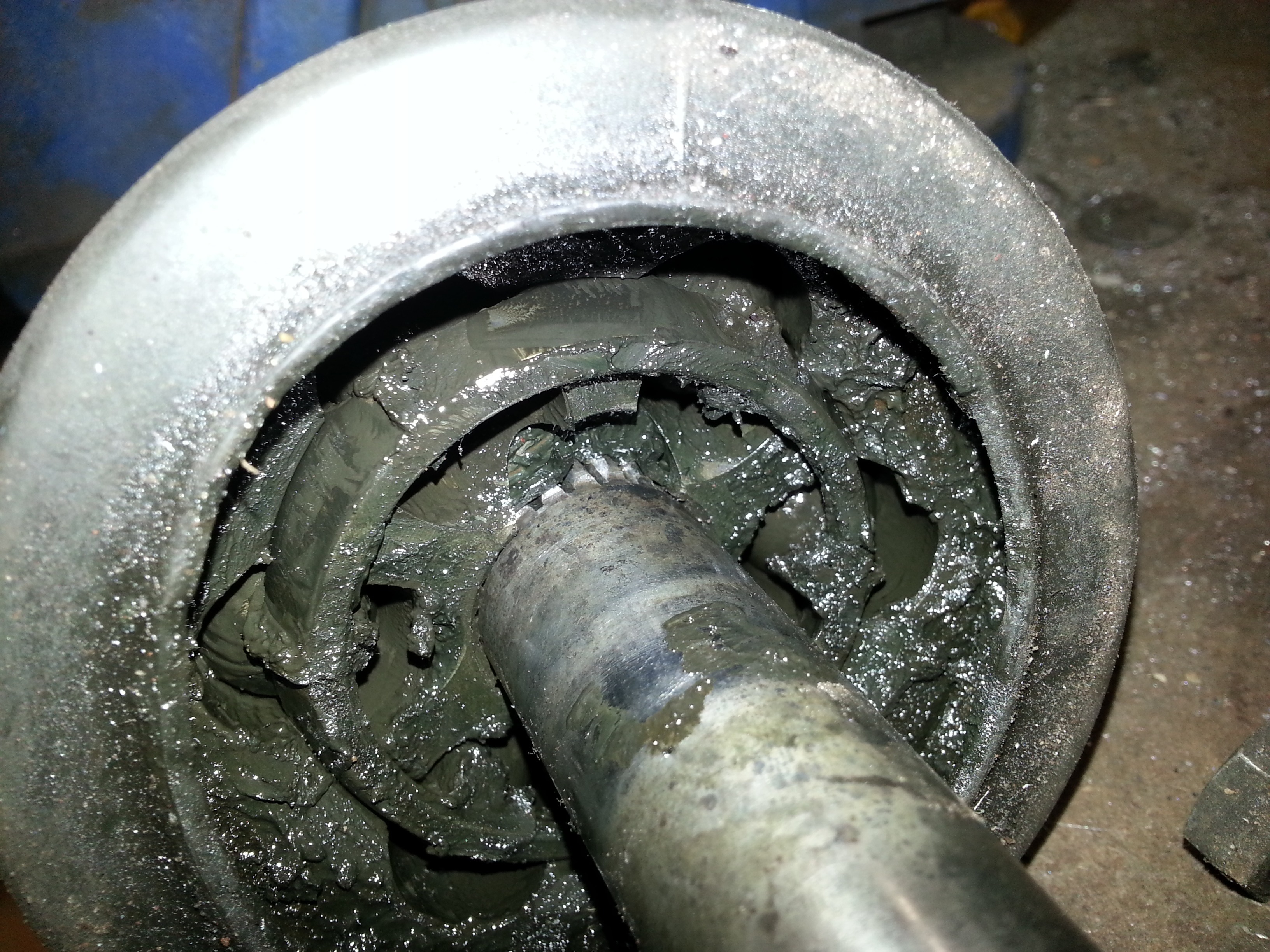
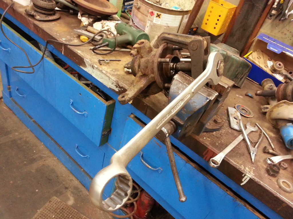
As a side note I want to mention that the wheel hub and CV joint were quite tight together and needed proper puller + some heat to take them apart:

20140731_194840

For rear diff I will use the Ka drive shaft and wheel hub with it’s bearings to mount it to the center of the frame where it will act as a cardan shaft output mount point (+center bearing bracket). For cardan shaft I will modify one from two Sierra’s cardan shafts. I take the longer part of Sierra’s rear cardan shaft and disconnect the shorter part from the joint.  That shorter part will be replaced with similar flange from other Sierra’s rear cardan shaft like used to connect it to the diff. Only new part needed for this is the universal joint since Ford has decided that you need to break the universal joint if you want to take Sierra’s cardan shaft to pieces. Similar way like to the front diff I will need one flange to be lathed which will connect Ka wheel hub to Sierra’s diff flange.

I also have been thinking and planning how to do the front axle wheel mounts and replace the suspension parts with some fixed stuctures. I come to a conclusion that I will most probably use Lada Niva ball joints for upper and lower joints. They are rather cheap to obtain and they have designed so that both upper and lower ball joint will carry the weight of the car (or tractor at this case). Usually the lower ball joint is not carrying the weight of the car, at least not as heavily than the upper one.
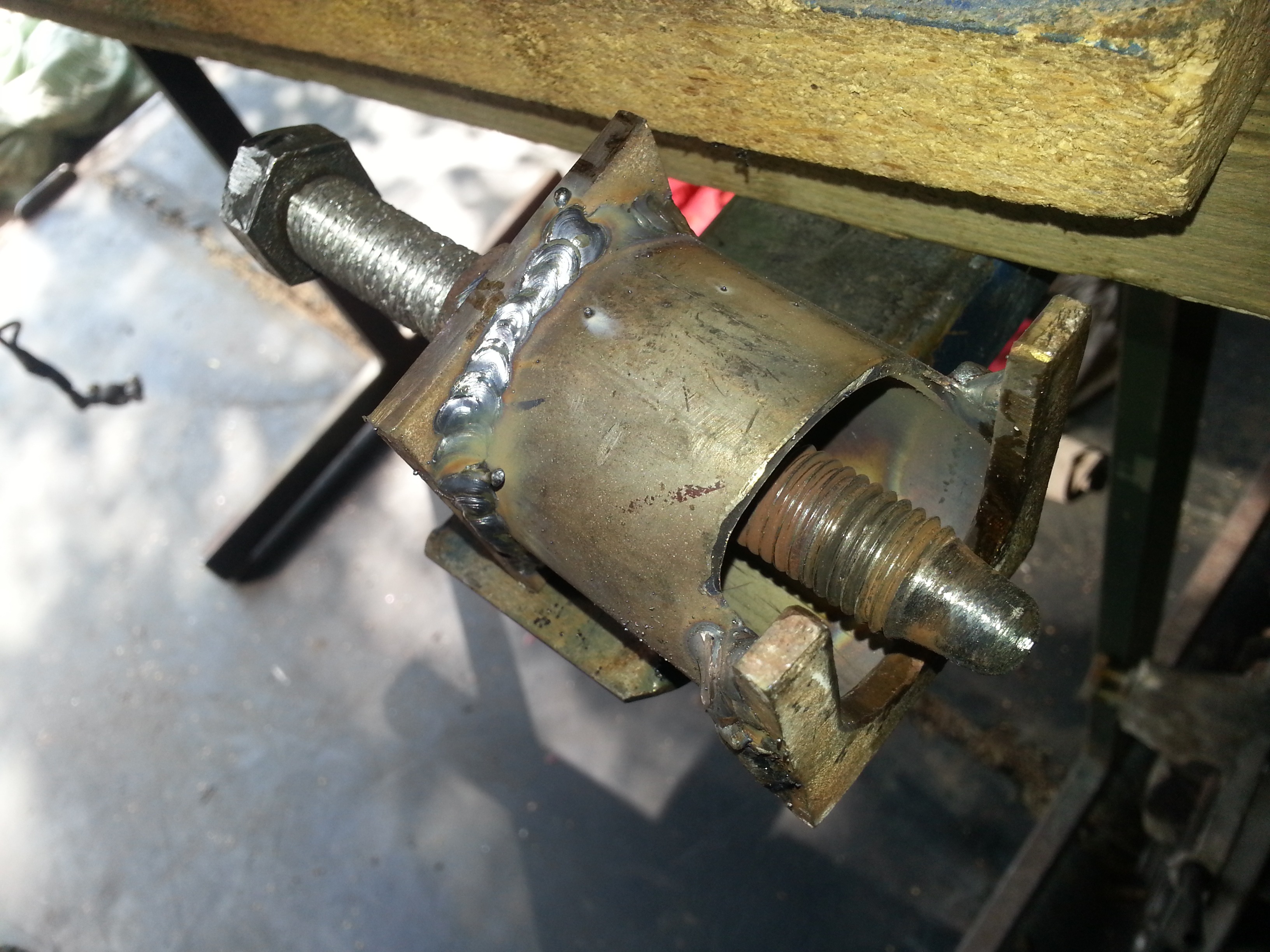
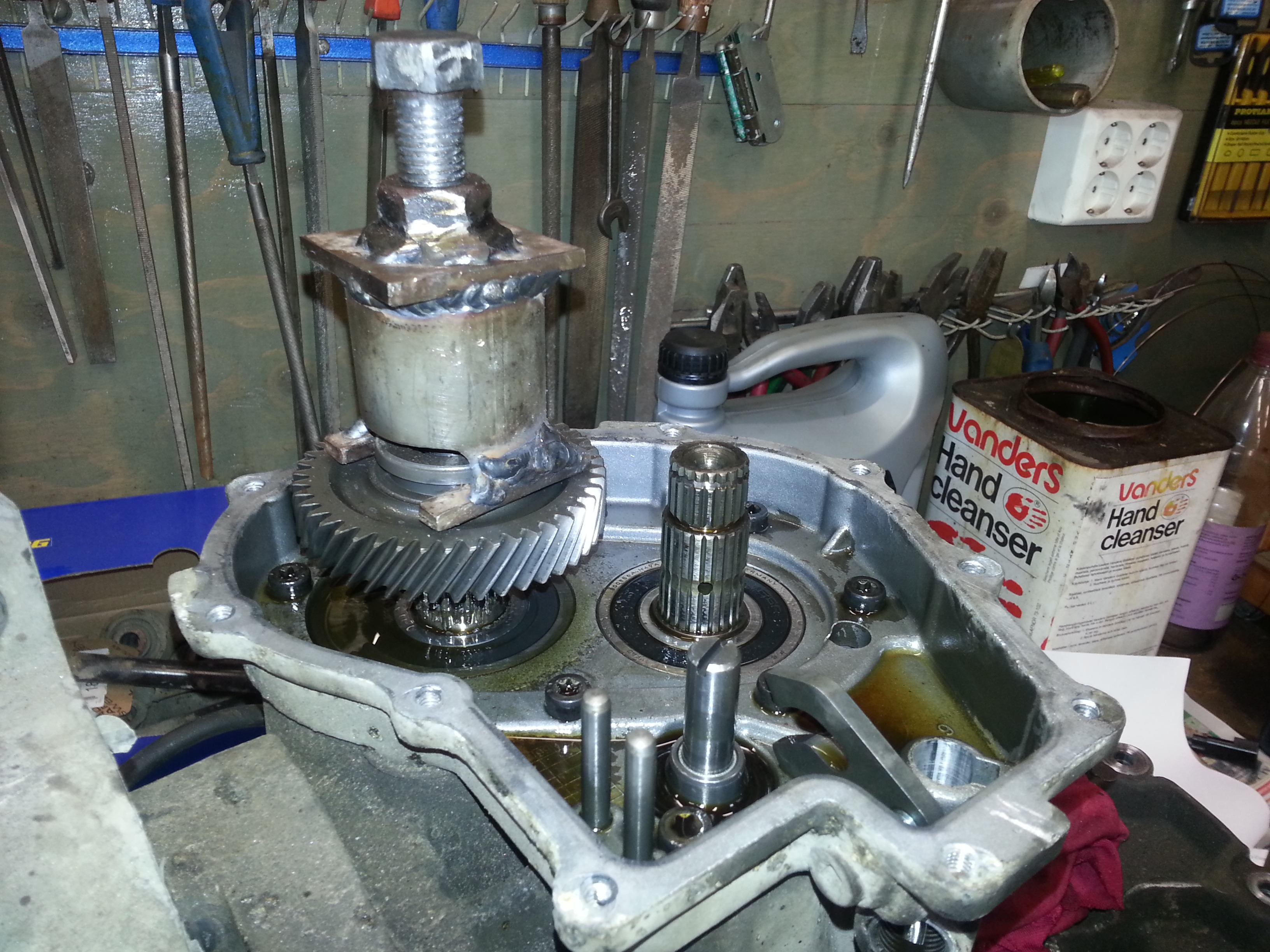
Pluggable Sierra driveshaft

Some people say that you cannot dismantle Sierra’s  plug-gable drive shafts, or actually they say that you cannot but it back together. I think they are wrong, even though I have no intention to put those drive shafts back to their original configuration.

But it is rather easy to take off the metallic cover by carefully bending it open piece by piece from the outer edge of the joint:

20140724_112143

I might have bend it even a big too much open than needed, but still that would be rather easy to put back together. If I needed to put it back together I would use some good glue instead of trying to press it in a form like it were mounted. I would just clean the grease off from the outer edge surfaces and apply some glue like Sikaflex 521 UV or similar. While the glue dries I would tighten it up with pipe band. But like I said I will not do this since I need to reconfigure this drive shaft for other configuration than it has meant to be.

Like the picture shows I recommend using some tape to keep the bearings in their place. If those go off you quite likely need to spend some not so enjoyable time to find all the needles from the floor that will drop off…

After you have taken the wheel mount off the rest will look like this:

20140724_112153

Tractor project recovered from a short hiatus

I got the BMW good enough shape even it took more time than I anticipated. Let’s see does it continue somehow at next summer or not…

But I started to collect tractor pieces about to their end locations:

20140722_144355 20140722_144202 20140722_144307

Unfortunately I got a flu and not feeling that energetic at the moment. Usually that won’t last long, but let’s see. I try to get some work done no matter of that, but probably I cannot do that long days I otherwise would like to do.

Tractor frame material aquired

Here is some 120x40x3 steel profile for the frame and also 40x40x3 + 20x20x2 for axles etc…

image

This Ka is a stub

Now Ka chassis is as small as I like it to be:

20140714_175145

Or at least I will not cut it any smaller before the frame starts to take a shape.

Unfortunately now this DIY Tractor project need to be a couple of days in hiatus since I need to install a couple of gadgets to my friend’s BWM. But I’m hoping to be able to continue this tractor project before the weekend already.

Ford Ka – The Flintstones Edition

Today I continued to cut the unnecessary pieces away:

20140713_202730 20140713_202816 20140713_202758

Technical diagram

Or actually a very high-tech diagram about the project:

image

Some scales are a bit off but this is the best project plan document I have. At least the front section may be a bit taller than pictured in this drawing. Also the front-end loader/ lifter is missing, but that will be planned later when the project starts to take more real shape.

Hopefully the ready product looks a bit more professional than this plan. 😛